Intact.Simulation Best Practices
Introduction
This document outlines best practices for using Intact.Simulation effectively and accurately. Whether you are a designer iterating quickly or an analyst validating results, this guide will help you choose appropriate simulation settings, understand how Intact’s mesh-free method works, and perform reliable benchmarking.
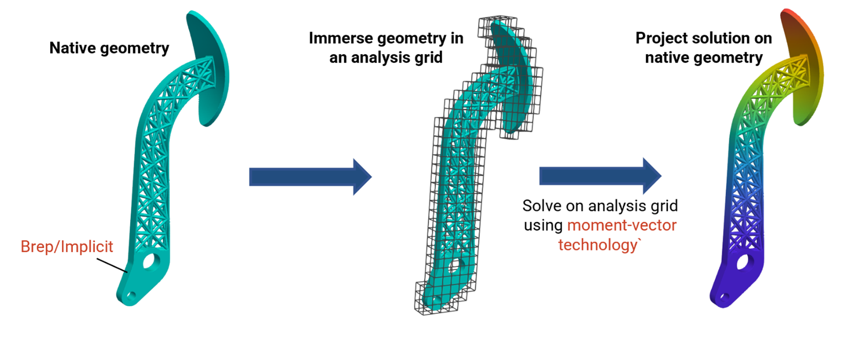
Intact.Simulation uses a novel mesh-free approach based on the Immersed Method of Moments (IMM), allowing simulations to run directly on native geometry without traditional meshing. This enables rapid iteration, reduces preprocessing effort, and provides robust results across a wide range of input formats.
1. Mesh-Free Simulation with Intact
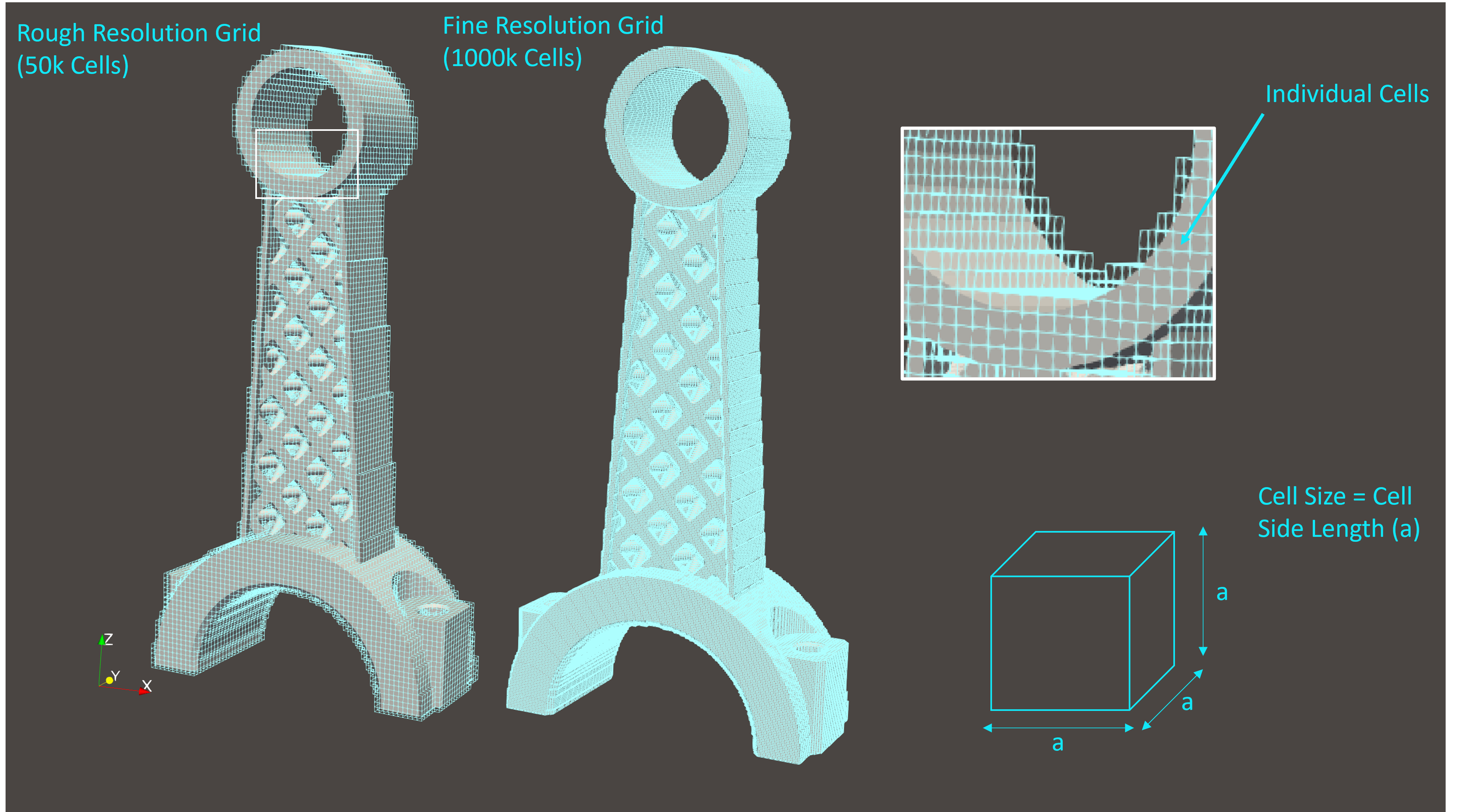
Non-conforming grid: Intact uses a structured, uniform orthogonal grid (3D cubes) rather than a conforming finite element mesh. Only the cells intersecting the geometry are included in the simulation.
Boundary conditions on geometry: Loads and constraints are applied directly to the faces of the geometry, not to mesh nodes.
IMM integration: Each intersected grid cell is numerically integrated using moment-fitting quadrature, ensuring accurate and stable results.
This mesh-free process eliminates meshing bottlenecks and supports native formats such as CAD, STL, implicit surfaces, voxel data, and CT scans.
Although Intact uses a mesh-free, geometry-agnostic integration method through IMM, the core of the solver is grounded in traditional finite element formulations. Once the custom quadrature rules are constructed for each intersected cell, Intact assembles and solves the linear system using conventional FEA techniques—ensuring compatibility with well-established theory and practices.
2. Choosing Simulation Settings
2.1 Resolution and Cell Size
Resolution refers to the total number of active grid cells (fully inside or intersecting the geometry).
Cell size is the edge length of each cube; smaller cell size results in higher resolution and accuracy but increased computational cost.
Rules of Thumb:
For linear elements: set cell size to 1/3 of the smallest feature to be accurately captured. This can be relaxed for early design-stage studies.
For quadratic elements: cell size can be ~1× the size of the smallest feature.
Typical Resolutions
Resolution |
Linear |
Quadratic |
|---|---|---|
Low |
10,000–100,000 |
1,000–50,000 |
Medium |
100,000–500,000 |
50,000–100,000 |
High |
500,000–2,000,000* |
100,000–200,000* |
* Maximum values depend on machine specs and problem complexity.
⚠️ Using too small a cell size can lead to excessively high DoFs—only increase resolution as needed for convergence.
2.2 Linear vs Quadratic Elements
Linear elements (default): Recommended for most general cases and complex geometries.
Quadratic elements: Ideal for problems dominated by bending or twisting (e.g., thin beams, plates, shells). Offer better accuracy with fewer elements, but are computationally more expensive.

✅ Tip: For bending-dominated problems, use at least 3 linear elements across the smallest cross-section or try quadratic elements.
2.3 Solver Choice
Direct solver: Faster and more accurate at low to medium resolutions. Recommended up to ~250k resolution on a 32 GB RAM machine.
Iterative solver: Better suited for high-resolution simulations where memory is a constraint.
3. Validating and Benchmarking Results
⚠️ Convergence studies are essential for ensuring accurate results. Adaptive refinement is under development and will simplify this process in the future. For now, follow these guidelines to maximize accuracy:
3.1 Displacement Convergence
Gradually increase resolution.
Track maximum displacement values across simulations.
Consider results converged when displacements stabilize within an acceptable tolerance.
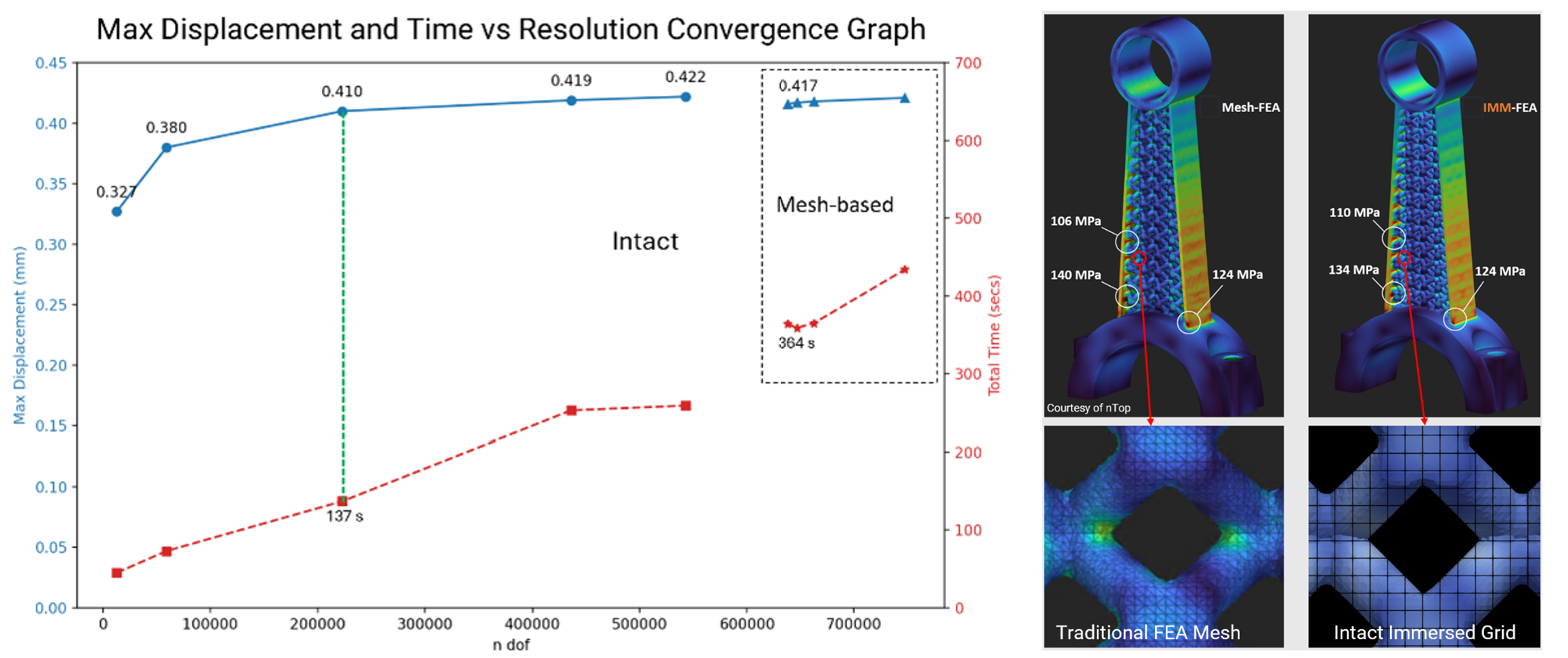
✅ With Intact, you can run low-resolution studies even on complex geometries that would be difficult to mesh in traditional FEA.
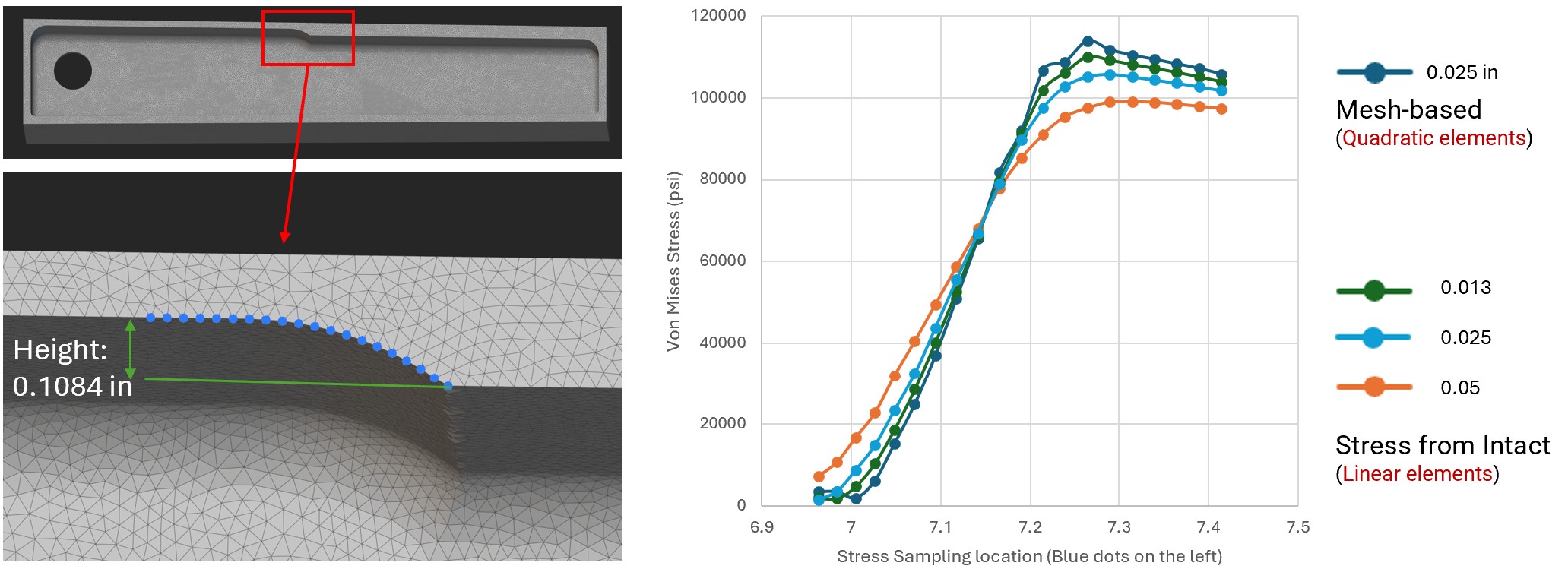
3.2 Stress Convergence
Avoid using maximum stress for validation (often occurs at singularities).
Evaluate stress at points of interest away from corners and sharp features.
Look for consistency in values as resolution increases.
3.3 Comparing with Mesh-Based FEA
Mesh-free methods typically require more elements than conforming meshes for matching stress results, especially near hot spots, since there are no boundary-conforming nodes. However, the reduction in meshing effort makes Intact significantly faster overall, particularly for complex designs.
For accurate stress comparison:
Use finer resolution with Intact.
Avoid comparing stress near stress singularities.
🛠 Note: Intact is developing adaptive refinement to reduce the need for manual convergence studies.
4. Common Pitfalls and Tips
Avoid starting with high resolution: Start small and scale up as needed.
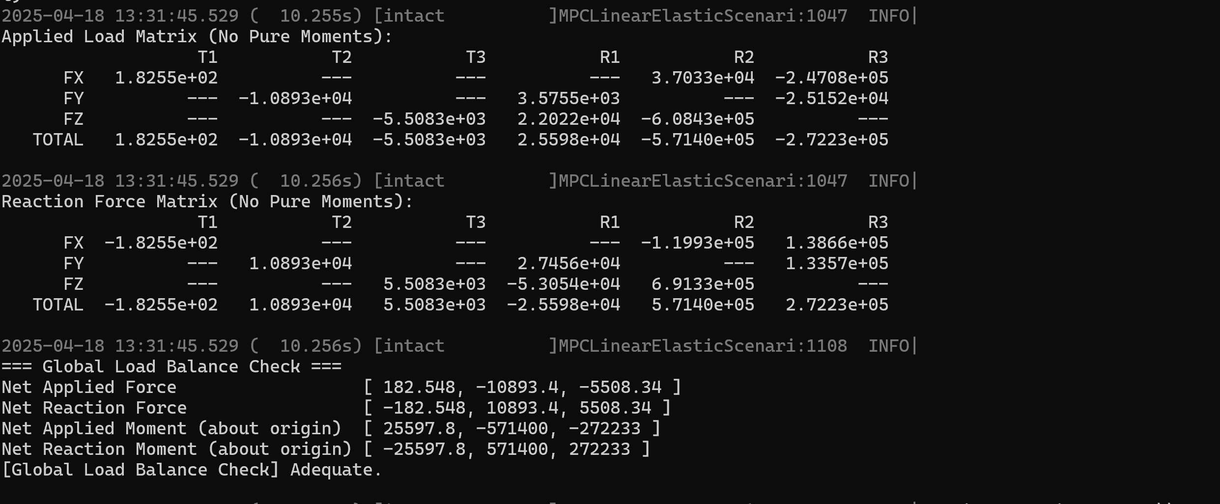
Misapplied boundary conditions: Always validate supports and loads. A quick low-resolution test run can help verify setup. Intact provides total applied load vector, reaction forces, and load balance check (See the Simulation Log). If your results look unexpected, confirming that the total reaction force balances the applied loads is a good diagnostic step.
Thin features not captured: Increase resolution or use quadratic elements.
For further assistance or a demo, email support@intact-solutions.com