
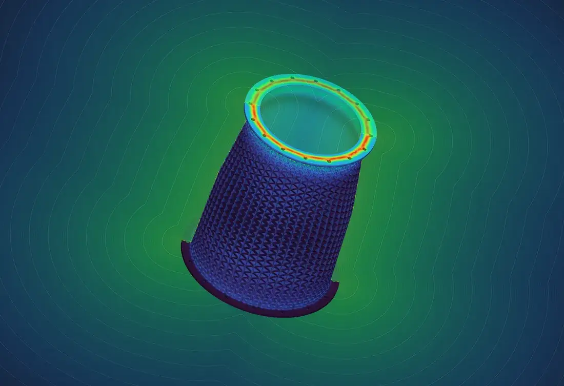
By working directly with the native nTop implicit, Intact.Simulation removes that translation step so the same geometry is used for design and analysis.
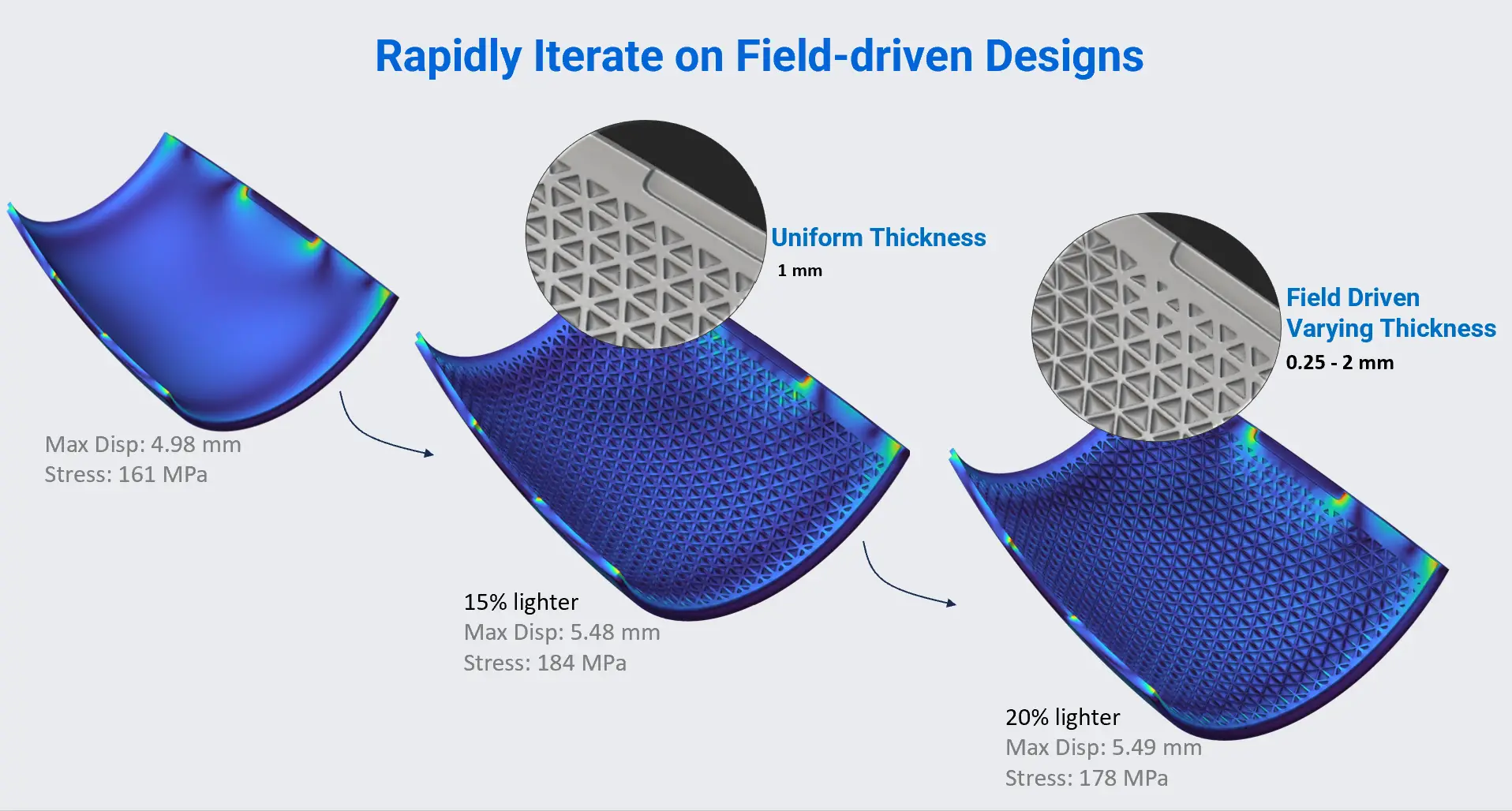
Field-driven geometry can change rapidly. Native implicit analysis allows physics to follow those changes without rebuilding the analysis representation each time.
01
Conventional CAE turns implicit complexity into a bottleneck
Most established CAE workflows expect explicit faces, edges, and vertices. Loads, restraints, contacts, material regions, and mesh controls are attached to that topology, and a finite-element mesh is generated to conform to it. Because an implicit body does not naturally fit this workflow, it must first be tessellated into a polygonal surface. A fine tessellation preserves more detail but creates large surface data and greater downstream cost, while a coarse tessellation is lighter but can distort or remove the small features that made the design valuable.
The converted surface must then survive cleanup, defeaturing, and body-fitted volume meshing. Lattices, thin ribs, small gaps, dense intersections, and large variations in feature scale make those steps difficult and unpredictable.
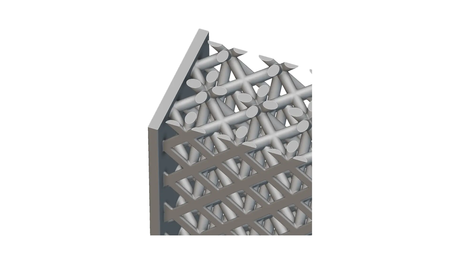
Implicit Representation
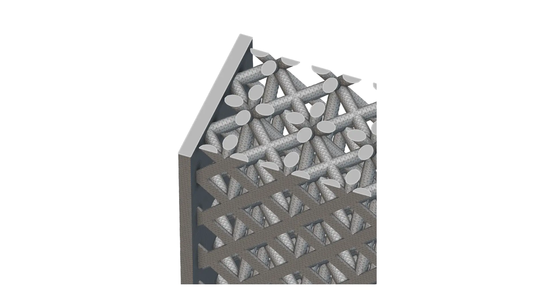
Surface Mesh Representation
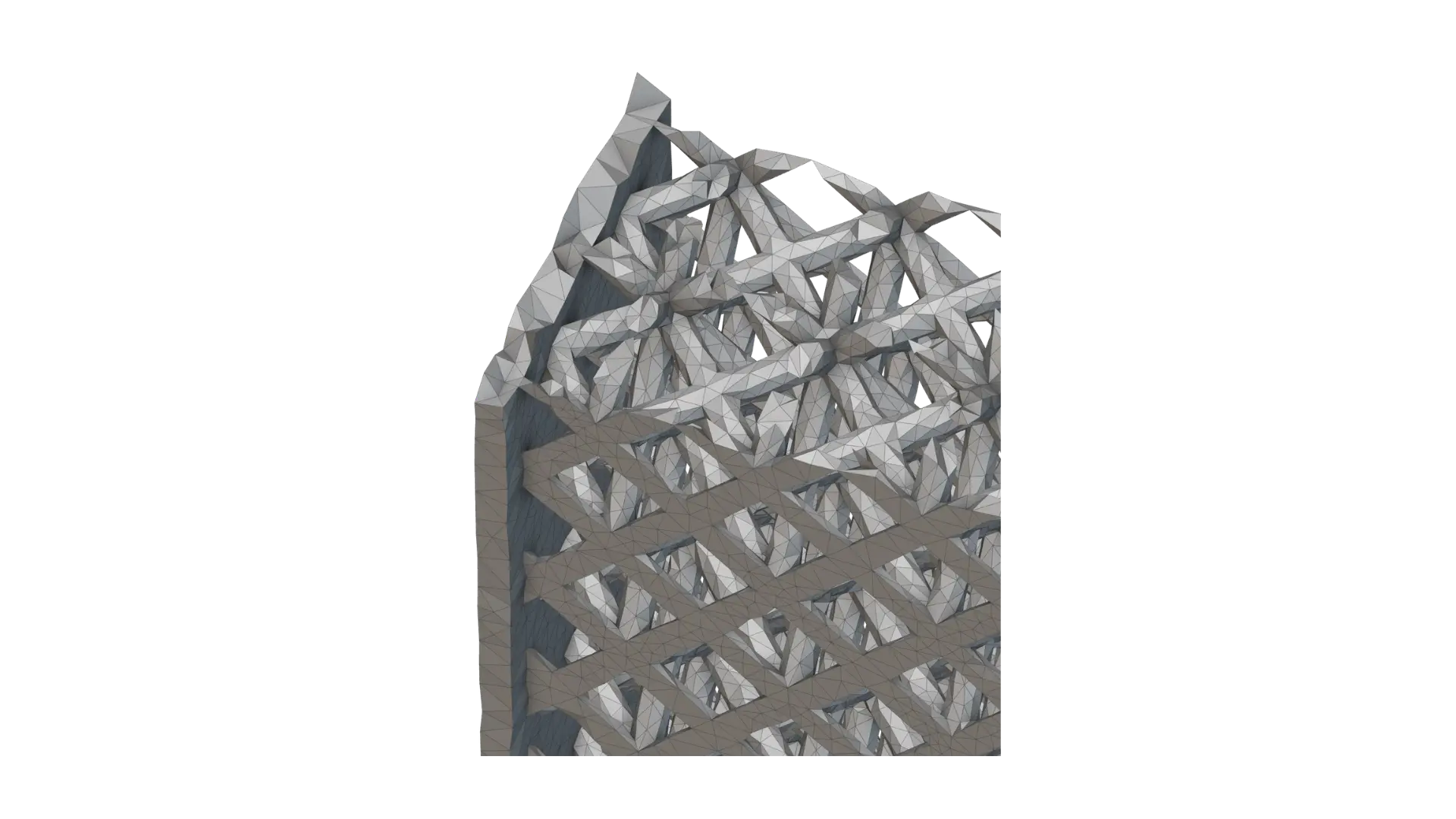
FEA Volume Mesh
In conventional CAE, the native implicit becomes an explicit surface mesh and then a body-fitted finite-element mesh before analysis can begin.
The cost extends beyond the initial setup because changing topology, cell size, rib count, thickness, or grading can invalidate the converted surface or mesh and trigger another round of manual work. A pipeline that depends on that intervention cannot reliably support DOE, optimization, or automated design exploration. In practice, the effective design space becomes smaller as engineers avoid designs that are difficult to push through downstream CAE, and simulation becomes a late validation step instead of an active part of design.
02
Intact.Simulation works directly with the native implicit
Intact.Simulation uses the Immersed Method of Moments (IMM) to analyze native nTop geometries. The implicit body is accessed through nTop Core and immersed in an independent background grid of hexahedral elements, allowing its boundary to pass through the elements instead of forcing a mesh to conform to the geometry. The analysis still uses a finite-element grid, but because it is generated independently of the geometry, the meshing process itself is eliminated.
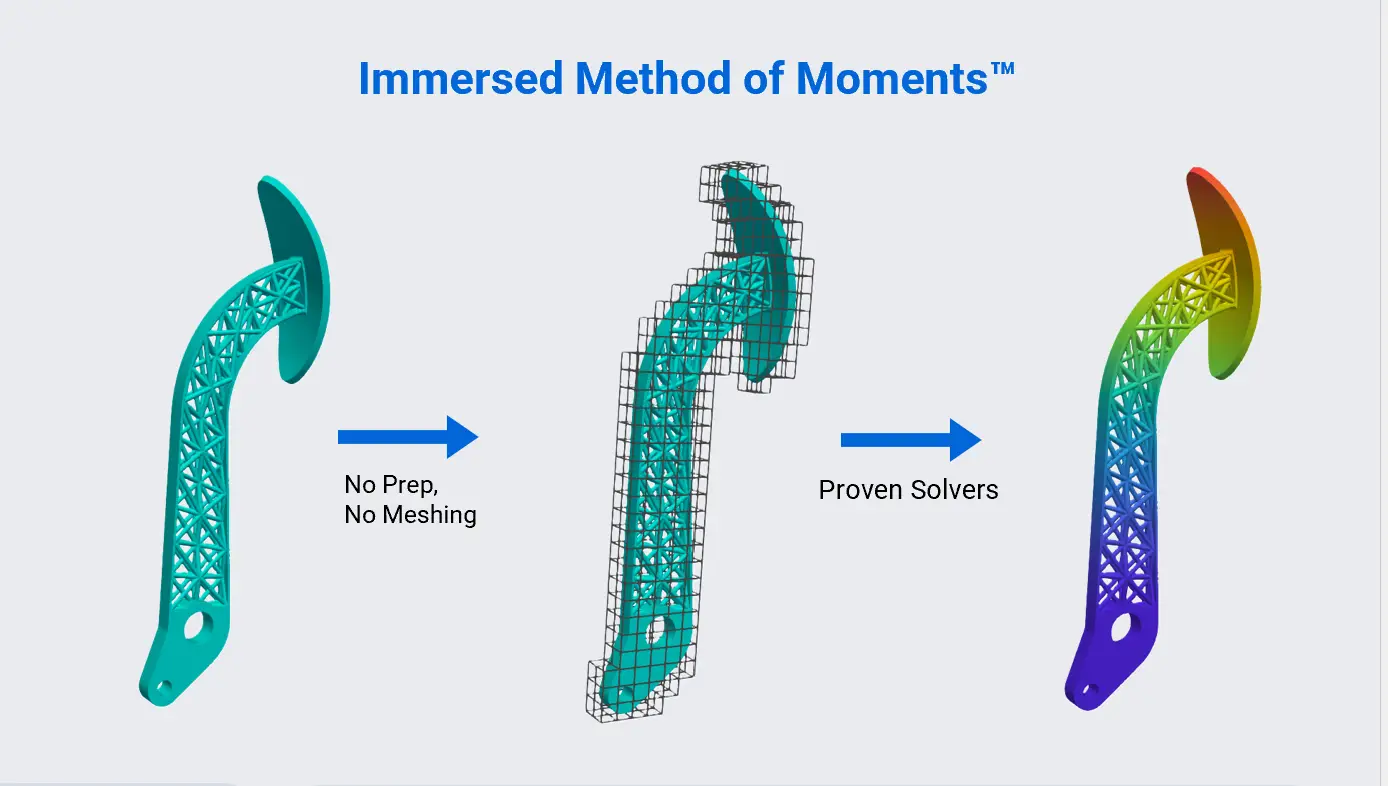
IMM places the native geometry inside an independent finite-element grid, eliminating analysis-specific geometry preparation and body-fitted meshing before assembly and solution.
Making this workflow accurate and usable requires two capabilities: integrating the field-defined volume and applying loads and restraints to meaningful regions of its surface.
2.1 Integrate the field-defined volume
nTop Core queries identify analysis cells that are inside the material, outside it, or cut by the implicit boundary. For cut cells, Intact recovers the geometric information needed for numerical integration, and moment-based integration computes the volume contributions used to assemble stiffness, mass, thermal terms, and the other quantities in the governing equations. The solver therefore integrates over the actual implicit domain while the analysis remains on the independent grid.
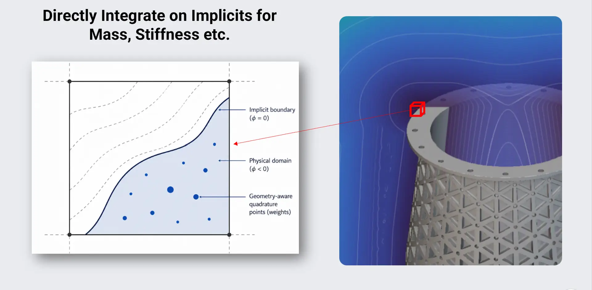
Geometry-aware integration: the implicit boundary is sampled and integrated directly within the analysis grid.
2.2 Apply boundary conditions to the implicit surface
When the model provides a suitable CAD face, such as a planar or cylindrical face, Intact can use it directly to define where a load or restraint acts. When no suitable CAD face is available, selection geometry identifies the region instead: a mask intersects the implicit boundary, and the portion inside the mask becomes the application region. In either case, Intact constructs the local surface information required for integration. For pressure, for example, that includes surface area and an oriented normal, which convert the scalar pressure into the correct distributed vector load.
Users can therefore express engineering intent, such as “apply pressure here” or “restrain this region,” directly on the implicit without creating an analysis-specific surface and mesh first.
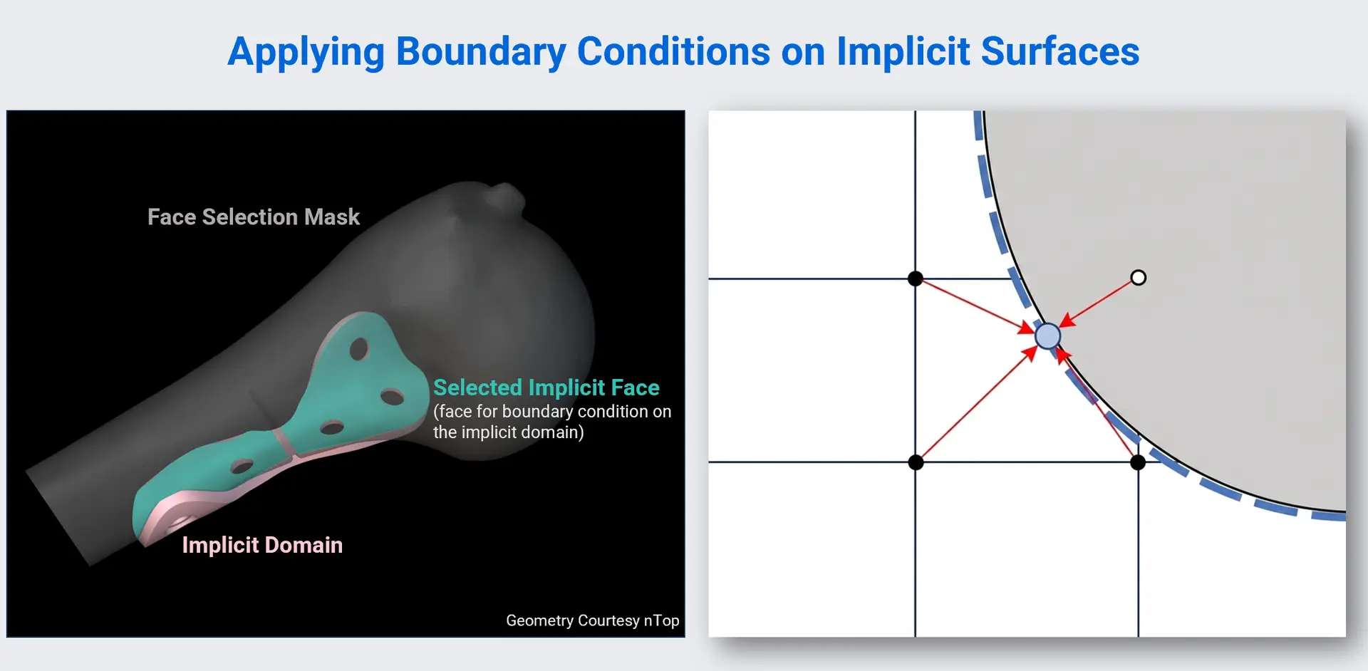
A selection region identifies the relevant portion of the implicit boundary; local surface information provides the area and normal required for loads such as pressure.
03
Accurate, fast FEA without a body-fitted mesh
Once the immersed grid, integration rules, and boundary conditions are established, the rest of the workflow is classical FEA: assemble the system, solve it, and post-process the results. Accurate treatment of the cut volume and implicit boundary allows IMM to converge under refinement and agree with mesh-based FEA when a body-fitted analysis is practical. In the connecting-rod example below, Intact and nTop FEA produced displacements of 0.422 mm and 0.421 mm, respectively, with reported stress values of 84 MPa and 88 MPa.
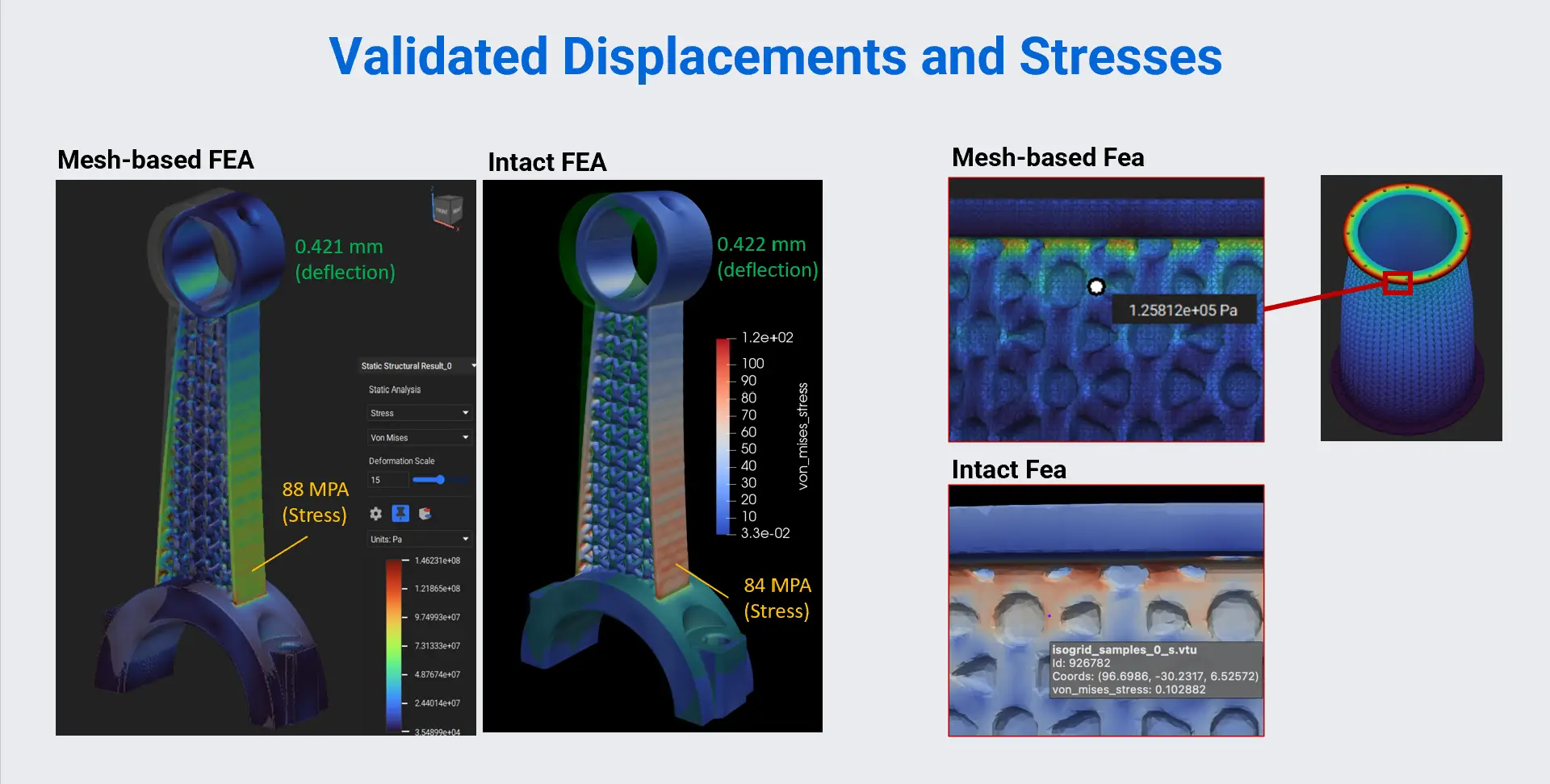
Intact and mesh-based FEA produce closely aligned displacement and stress results.
An independent grid also makes analysis resolution a direct user control: coarse resolutions provide fast directional feedback, while finer resolutions systematically refine the answer without rebuilding a geometry-conforming mesh. In the benchmark below, displacement converges toward the mesh-based result as the number of degrees of freedom increases, and the tested Intact resolutions complete in less total time than the mesh-based runs.
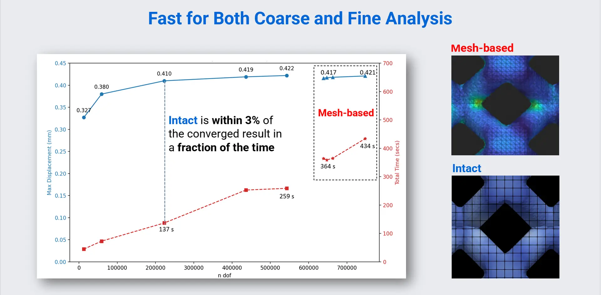
At 137 seconds, Intact is already within 3% of the converged displacement—less than 40% of the fastest mesh-based run time—and further refinement closes the remaining gap.
04
Native physics unlocks the implicit design workflow
By operating on geometry that is complex, changing, and programmable, direct implicit analysis both makes difficult models solvable and brings simulation into the computational design workflow.
4.1 Analyze geometry that cannot be easily meshed
Intact.Simulation can evaluate lattices, dense ribs, small gaps, and large variations in feature scale without simplifying them into mesh-friendly geometry. The lattice block and web-ribbed housing below are examples for which producing a suitable conventional mesh was not practical; Intact analyzes their native implicit representations directly.
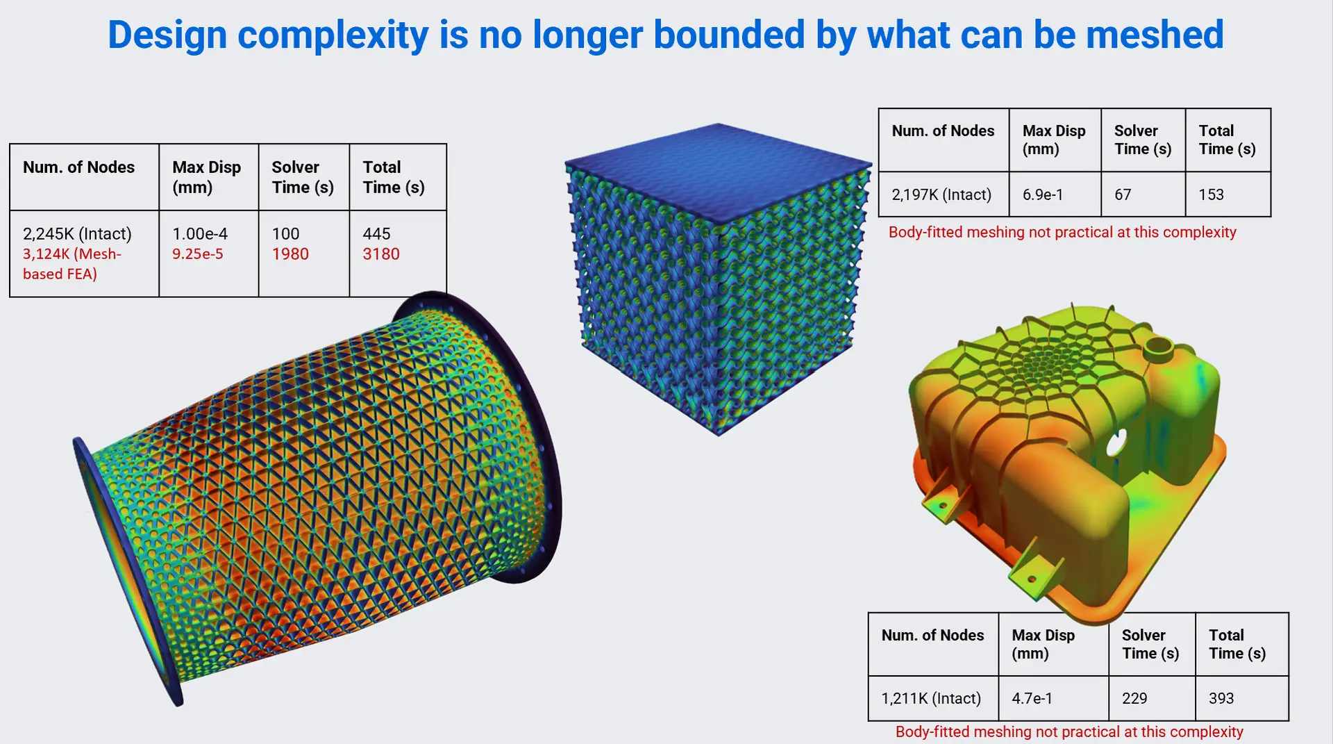
The Iso-grid provides the same results in a fraction of the time compared to the mesh-based simulation. The lattice block and housing show geometry for which conventional meshing was not practical.
4.2 Iterate without rebuilding the analysis representation
When parameters, fields, or topology change in nTop, Intact.Simulation can analyze the updated implicit without regenerating, repairing, and validating a separate surface conversion and body-fitted mesh for every candidate. Physics can therefore enter while the design is still being generated, allowing engineers to evaluate lattices, graded structures, and field-driven reinforcements without first simplifying them for the analysis tool.
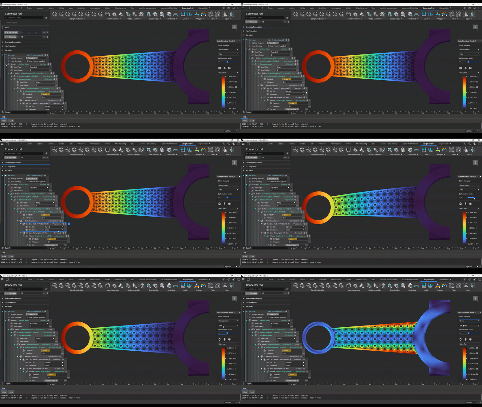
Simulation reruns automatically as you iterate through design parameters.
4.3 Scale to DOE, optimization, and closed-loop design
A workflow that survives geometric changes can run repeatedly without manual intervention, making it practical to explore how design parameters affect stiffness, stress, thermal performance, mass, or other engineering objectives across many candidates. nTop generates the geometry programmatically, Intact.Simulation evaluates it headlessly, and the results can drive the next parameter update, optimization step, surrogate model, or automated decision.
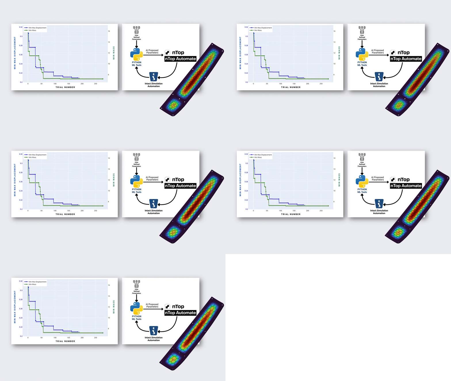
Headless execution of Intact and nTop for autonomous, agentic, and computational workflows: nTop Automate generates each design, Intact.Simulation evaluates it headlessly, and Python or ML tools use the results to propose the next set of parameters.
4.4 Use nTop Fluid results directly as structural loads
nTop Fluid produces spatially varying pressure results as implicit fields. Intact.Simulation evaluates the pressure field directly on the native implicit boundary, combining each local pressure value with the surface area and normal to assemble the distributed structural load. This avoids generating a transfer mesh, matching nodes, or interpolating results between unrelated fluid and structural meshes.
The same field-based connection can also transfer temperature results into thermal and thermo-mechanical studies. Models with complex aerodynamic surfaces or internal flow passages can therefore move from fluid analysis to structural or thermal analysis without abandoning the native implicit representation.
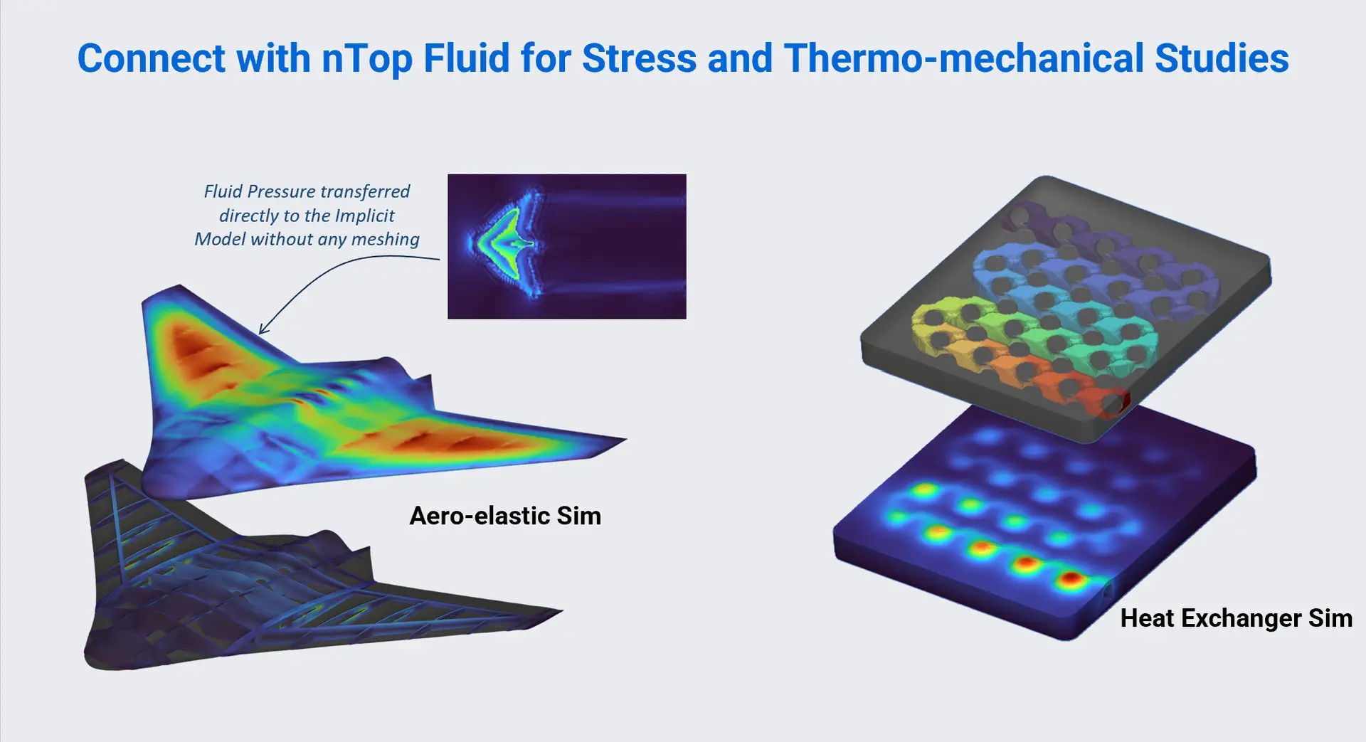
Pressure and temperature fields from nTop Fluid can drive structural and thermo-mechanical studies without an intermediate mesh-transfer workflow.
THE TAKEAWAY
Keep the implicit native from design through physics
Implicit design should not have to be converted to conventional geometry before it can be analyzed. Intact.Simulation connects directly to the nTop implicit model, integrates its volume, applies boundary conditions to its surface, and produces first-principles engineering results without body-fitted meshing.
That preserves the real advantage of implicit modeling: not simply complex shapes, but a design representation that can change, iterate, and scale.