Overview
- Current simulation methods require meshing which is a time-consuming process and often requires manual intervention, breaking automation in computational design tools. This severely limits the capabilities of both the designers and the design tools.
- Intact.Simulation can run automated simulation in a loop with no manual intervention, empowering your design applications and unlocking the creative powers of the designers.
- This blog demonstrates Intact.Simulation’s automation capabilities by simulating around 300 designs from GE bracket challenge automatically in a loop.
Simulation Bottlenecks are Stifling Design Tools and Designers
Modern computational design tools, including Generative AI, can help explore vast design spaces, but only if the generated designs can be automatically simulated, tested, and validated.
The capability of the tools are being restrained by the bottlenecks of the current simulation technology, which require (volumetric) meshing, where the mesh has to adapt to the smallest features.
❌ Meshing parts, specially latticed parts, could take hours, if not days, depending on the geometric complexity.
❌ Users have to convert their native geometric representation into FEA meshes, which usually requires defeaturing the parts, dimension reduction, and other geometric simplifications.
This often involves human in the loop and requires judgement and experience.

With Intact.Simulation, you can run automated simulation in a loop with no manual intervention, empowering your design applications and unlocking the creative powers of the designers.
✅ No preprocessing and meshing bottlenecks
✅ Simulate native representations without conversion
✅ Seamlessly integrate to your design workflows
Without any meshing, preprocessing, or human in the loop, Intact.Simulation scales to evaluate and optimize thousands of designs at a push of a button.
Automated Simulation of Designs from GE Bracket Challenge
In the current blog, we demonstrate the automation capability of Intact.Simulation for the popular GE bracket challenge competition. The challenge is to design a lightweight part that can withstand multiple different loading conditions. The SimJEB GitHub repository has a collection of a subset of the submissions. In this blog, we demonstrate Intact.Simulation’s capability to run simulations on a large number of designs automatically (“in a loop”) by testing almost 300 of the designs from the SimJEB repository.
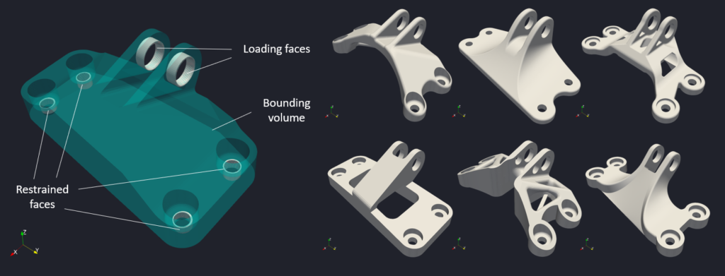
The SimJEB GitHub repository has a collection of a subset of the total submissions. The authors of this dataset have converted a subset of the submissions so that they are all in the same coordinate system, units (mm), and the same representation (OBJ surface meshes). The goal is to test the samples in the dataset for a loading condition as shown in the picture below.
Simulation Assumptions:
- The material is Aluminum
- A load of 5000 N is applied in the [1,0,1] direction
- The cylindrical faces at the bottom are restrained

Seamless automation with Intact.Simulation
Intact.Simulation’s Immersed Method of Moments technology is based on a decoupled geometry-FEA framework. This implies that the boundary conditions are to be applied independently of the analysis geometry. 🔆 In other words, the boundary conditions can be defined using standard geometry files (e.g., CAD/STL) while the analysis geometry can be in any other format (CAD/STL/voxels/implicit, etc.). Consequently, we can keep the same boundary condition setup and swap out different geometries and analyze them.
✅ This process can be completely automated! A simple Python code snippet as shown below should accomplish this.

In the above code snippet, the sample geometry files are stored in the list sample_geometries. The boundary condition data (loads, restraints) are the same for all the sample geometries. The assemble_json() function creates the JSON input file for the geometry sample, which is sent to intact.exe for simulation. A snippet of the JSON input for boundary conditions is shown below.

Results
We analyzed the samples in the dataset and saved the simulation results. The von Mises stress distribution for the samples is shown in the animation below.
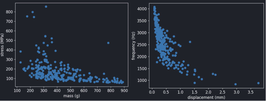
We can also easily query the simulation data for max. von Mises stress, max. displacement, first natural frequency. A scatter plot of stress vs mass and frequency vs displacement is shown below. The general trend that we can see from the pictures below is that (a) the heavier designs have lower max. stress values and (b) the first frequency is negatively correlated with maximum displacement.

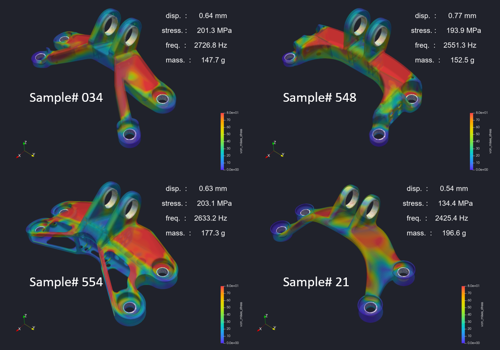
From the above samples, the following 4 designs meet the following criteria
- Max. displacement should be approximately less than 0.8 mm
- Max. Von Mises stress should be approximately less than 200 MPa
- The first frequency should be at least 2500 Hz
- Mass should be approximately less than 200g

Summary
This blog post demonstrates the power of Intact.Simulation’s technology in automating simulation.
- Conventional FEA tools face challenges in automating simulation due to the time-consuming meshing process and manual conversion of boundary conditions.
- Intact.Simulation’s Immersed Method of Moments technology allows for seamless simulation automation using a decoupled geometry-FEA framework.
As a demonstration Intact.Simulation’s automation capabilities, we explore the robustness of designs submitted for the GE bracket challenge problem by testing whether they can sustain a different loading condition.
- We show how to automate the simulation for all the designs using a simple Python code snippet.
- We also show the simulation results, including stress vs. mass and frequency vs. displacement scatter plots to identify designs that meet specific criteria.
Please contact info@intact-solutions.com to get a copy of the related files presented in this article or have any questions about Intact.Simulation for Automation.