Table of Contents
Overview of Controls
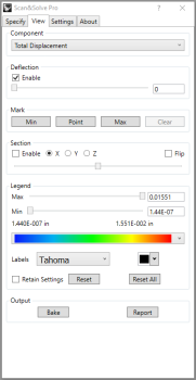
All controls in Scan&Solve Pro are aggregated in four tabs: Scenario Selector tab for reviewing past scenarios or creating new ones, Specify Tab for setting up the analysis problem, View Tab for visualizing the computed solution, and Settings Tab for adjusting simulation parameters.
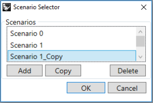
Scenario Selector
If simulations have been previously run on the model, the scenario selector window pops up when you prompt SnSPro in the command line. New scenarios can be added and past scenarios can be reviewed, edited, copied, or deleted.
[Add] - add a new scenario
[Copy] - copy an existing scenario to a new scenario for further editing
[Delete] - delete selected scenario
[OK] - open selected scenario
[Cancel] - exit out of Scan&Solve
Watch Intact Solutions' video “Getting Started with Scan&Solve Pro Part 1: Simulation Setup” from 0:26 to learn more about the scenario selector window.
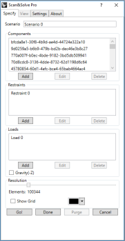
Specify Tab
The specify tab is where the simulation setup is performed. All the tools for adding, editing, and deleting components, restraints, and loads are located on this tab.
Components Group
Components must be closed valid solid objects in Rhino including closed solid meshes, closed valid polysurfaces, and solid extrusion objects.
- [Add] - add a component to the scenario.
- [Edit] - edit the material that comprises the selected component(s).
- [Delete] - remove the selected component from the scenario.
Watch Intact Solutions' video “Getting Started with Scan&Solve Pro Part 1: Simulation Setup” from 1:21 to learn more about adding components and materials.
Restraints Group
- [Add] - add a restraint to the scenario.
- [Edit] - edit the definition of the selected restraint.
- [Delete] - delete the selected restraint from the scenario.
Watch Intact Solutions' video “Getting Started with Scan&Solve Pro Part 1: Simulation Setup” from 2:46 to learn more about applying restraints.
- [Add] - add a load to the scenario.
- [Edit] - edit the definition of the selected load.
- [Delete] - delete the selected load from the scenario.
Watch Intact Solutions' video “Getting Started with Scan&Solve Pro Part 1: Simulation Setup” from 3:31 to learn more about applying loads.
Resolution
- [Slider] - adjust the slider to specify the simulation resolution.
- [Show Grid] - checkbox enables/disables display of the solution grid during simulation setup and visualization.
- [Grid Color] - button selects the color used for displaying the solution grid.
Watch Intact Solutions' video “Getting Started with Scan&Solve Pro Part 1: Simulation Setup” from 6:46 to learn more about adjusting the resolution.
Controls
- [Go!] - begin the simulation solving process.
- [Done] - finish working with scenario, save and close SnSPro.
- [Purge] - clear solution results to save space.
- [Cancel] - exit SnSPro without saving.
View Tab
Component Group
 The components group allows selection from the available solution quantities.
- [Enable Deflection] - checkbox toggles the display of magnified deflection.
- [Deflection Slider] - adjusts the deflection scale factor.
- [Deflection Edit Box] - allows entry of deflection scale factor and displays.
Watch Intact Solutions' video “Getting Started with Scan&Solve Pro Part 2: Analyzing Results” from 0:52 to learn more about using the deflection slider.
Mark Group
- [Min] - mark the location and value of the minima of the current solution quantity.
- [Point] - mark the value of the current solution quantity at a user-defined point.
- [Max] - mark the location and value of the maxima of the current solution quantity.
Watch Intact Solutions' video “Getting Started with Scan&Solve Pro Part 2: Analyzing Results” from 1:09 to learn more about the mark group.
Section Group
- [Enable Section] - checkbox toggles the section plane on/off.
- [Section Slider] - adjust the slider to position the section plane.
- [X] [Y] [Z] - radio buttons set the orientation of the section plane.
- [Flip] - checkbox flips the visible side of the section plane.
Watch Intact Solutions' video “Getting Started with Scan&Solve Pro Part 2: Analyzing Results” from 2:09 to learn more about using section views.
Legend Group
- [Max Slider] - adjust the legend upper limit.
- [Max Edit Box] - allows entry of legend upper limit and displays.
- [Min Slider] - adjust the legend lower limit.
- [Min Edit Box] - allows entry of legend lower limit and displays.
- [Legend ComboBox] - selects the current legend color scheme.
- [Font ComboBox] - selects the font for the legend labels.
- [Color ComboBox] - selects the color for the legend labels.
- [Retain Settings] - checkbox controls whether legend settings are retained between simulations.
- [Reset] - button resets the legend settings to the default for the currently displayed solution component.
- [Reset All] - button resets the legend settings to the default for all the solution components.
Other Controls
- [Bake] - bake the visualization mesh to the Rhino document or an external file. (More...)
- [Report] - generate a web-ready report of the simulation results. (More...)
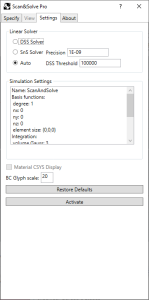
Settings Tab
The settings tab provides advanced controls for the simulation. To learn more about the Settings Tab, watch Intact Solutions' video “Getting Started with Scan&Solve Pro Part 1: Simulation Setup” from 7:20.
Linear Solver radio buttons control the linear solver used to compute the simulation results.
- [DSS Solver] - The direct sparse solver is very fast but because it can consume large amounts of memory it is best used on simulations at resolutions less than 100000.
- [SnS Solver] - The Scan&Solve solver is the default iterative solver that allows visual feedback of the solution progress.
- [Auto] - Runs with DSS Solver when resolution is below the threshold value. Otherwise, the SnS Solver is used.
Precision - this value controls the relative error tolerance at which the SnS solver considers a simulation completed. Smaller values increase solution accuracy at the expense of solving time.
DSS Threshold - specify the resolution value to switch to SnS Solver when under [Auto] mode.
Simulation Settings Group
The current simulation settings are displayed in this listbox.
Other Controls
- [Material CSYS Display] - this checkbox toggles display of the material coordinate systems.
- [BC Glyph scale] - the scale setting controls the size of boundary condition annotations as a percentage of the bounding box diagonal enclosing the simulation components.
- [Restore Defaults] - reset the simulation settings to their default values.
- [Activate] - use this button to activate the Scan&Solve license.


