Table of Contents
Using Orthotropic Materials
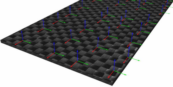
Scan&Solve Pro has the ability to analyze orthotropic materials such as composites where the mechanical properties of the material vary depending on orientation. The material orientation for orthotropic materials and composites is defined by the longitudinal direction of the fibers and the thickness direction of the laminate. These directions are described by a coordinate system with Axis 1 (red) aligned along the fibers, Axis 2 (green) aligned along the tangential direction, and Axis 3 (blue) in the direction of thickness stackup of the laminate. To view, toggle the display of the material coordinate systems from the Settings Tab.
In the example below, a carbon fiber plain weave is shown. The two orthogonal directions of the weave in-plane are indicated by the red and green arrows (longitudinal and tangential, respectively). The direction of thickness is indicated by the blue arrows.
Orthotropic Material Tab
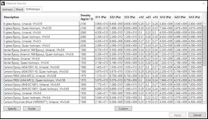
Orthotropic materials are selected from the Orthotropic tab in the Material Selector. A variety of composite materials are included in Scan&Solve Pro. Additional materials may be added by selecting the Custom button at the bottom of the screen and using the Material Editor.
The description indicates whether the material is uniaxial (fibers only run in one-direction, the longitundinal direction) or quasi-isotropic (composite laminate has fibers running in multiple directions, typically oriented in 45 degree increments). The quasi-isotropic materials have the same elastic modulus in the longitudinal and tangential directions. Lastly, the “Vf” value indicates the volume proportion of the material that is fiber, with the rest of the volume is assumed to be the matrix (resin).
The orthotropic material properties are defined according to the axis convention listed above. Elastic modulus, Poisson's ratio, and shear modulus are listed for the three principal dircections of the material.
Orthotropic Material Coordinate System
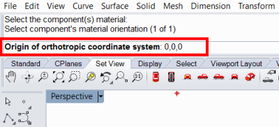
Once the material is selected, the material coordinate system can be specified. If the fiber direction does not change within the component, then the Specify option may be chosen. Then the longitudinal and thickness directions relative to a chosen origin point are entered by picking points on the screen or entering coordinates into the command window.
If the fiber direction changes throughout the compenent, then the Guide option must be used. This option requires a surface to define the thickness direction of the component. The direction normal to the guide surface will be the thickness direction. A curve to define the longitudinal direction must also be specified. For an example of using a guide surface, see Using Wood Materials.
It is often convenient to use the “Extract Face” feature to create a guide surface for the component.


